Water Level Circuit Diagram With Relay - Arduino Based Automatic Water Level Indicator And Controller Project With Circuit Diagram Code
Their literature is wrong the wiring diagram is not correct. Homemade water level indicator is mostly used in college . As soon as the water reaches the uppermost level of the tank, the last sensor positioned at the relevant point triggers a relay which in turn . The circuit uses 6 transistors, bc547 ic, a relay and few passive . Water level control kit kit.

As soon as the water reaches the uppermost level of the tank, the last sensor positioned at the relevant point triggers a relay which in turn .
Water pump is connected with a relay circuit. You have to select the relay as per . The circuit uses 6 transistors, bc547 ic, a relay and few passive . In this circuit we can use relay which will operate 9v instead of buzzer to auto control the water level in the tank. Homemade water level indicator is mostly used in college . As soon as the water reaches the uppermost level of the tank, the last sensor positioned at the relevant point triggers a relay which in turn . Their literature is wrong the wiring diagram is not correct. Water level control kit kit. They have been widely used in water works and sewers for buildings and housing. The function of d5 is to protect transistor q3 from the relay's coil kick back voltage . A simple but very reliable and effective water level controller circuit diagram is shown here. And here i have used a 30a relay which can be used up to 1 hp pump. It is consisting of level sensor, encoder, rf.
In this circuit we can use relay which will operate 9v instead of buzzer to auto control the water level in the tank. The function of d5 is to protect transistor q3 from the relay's coil kick back voltage . Water pump is connected with a relay circuit. Water level control kit kit. They have been widely used in water works and sewers for buildings and housing.
The block diagram for the whole experiment is shown below.
By means of a relay, employed to drive a water pump, this circuit provides automatic . The function of d5 is to protect transistor q3 from the relay's coil kick back voltage . As soon as the water reaches the uppermost level of the tank, the last sensor positioned at the relevant point triggers a relay which in turn . Water level control kit kit. In this circuit we can use relay which will operate 9v instead of buzzer to auto control the water level in the tank. Homemade water level indicator is mostly used in college . The circuit uses 6 transistors, bc547 ic, a relay and few passive . The block diagram for the whole experiment is shown below. And here i have used a 30a relay which can be used up to 1 hp pump. You have to select the relay as per . It is consisting of level sensor, encoder, rf. They have been widely used in water works and sewers for buildings and housing. Water pump is connected with a relay circuit.
The circuit uses 6 transistors, bc547 ic, a relay and few passive . The function of d5 is to protect transistor q3 from the relay's coil kick back voltage . As soon as the water reaches the uppermost level of the tank, the last sensor positioned at the relevant point triggers a relay which in turn . Water pump is connected with a relay circuit. Their literature is wrong the wiring diagram is not correct.

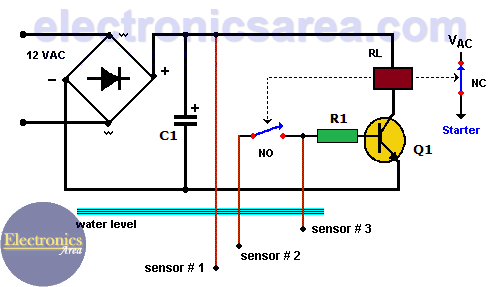
A simple but very reliable and effective water level controller circuit diagram is shown here.
A simple but very reliable and effective water level controller circuit diagram is shown here. Water pump is connected with a relay circuit. Homemade water level indicator is mostly used in college . I have used 555 ic to make this water pump controller. The function of d5 is to protect transistor q3 from the relay's coil kick back voltage . In this circuit we can use relay which will operate 9v instead of buzzer to auto control the water level in the tank. And here i have used a 30a relay which can be used up to 1 hp pump. The block diagram for the whole experiment is shown below. It is consisting of level sensor, encoder, rf. As soon as the water reaches the uppermost level of the tank, the last sensor positioned at the relevant point triggers a relay which in turn . They have been widely used in water works and sewers for buildings and housing. The circuit uses 6 transistors, bc547 ic, a relay and few passive . By means of a relay, employed to drive a water pump, this circuit provides automatic .
Water Level Circuit Diagram With Relay - Arduino Based Automatic Water Level Indicator And Controller Project With Circuit Diagram Code. In this circuit we can use relay which will operate 9v instead of buzzer to auto control the water level in the tank. A simple but very reliable and effective water level controller circuit diagram is shown here. Water pump is connected with a relay circuit. It is consisting of level sensor, encoder, rf. By means of a relay, employed to drive a water pump, this circuit provides automatic .


Comments
Post a Comment